
Команда sweep в автокаде
Обновлено: 07.07.2024
By:
Creates a 3D solid or 3D surface by sweeping a 2D object or subobject along an open or closed path.

Open-ended objects create 3D surfaces, while objects that enclose an area can be set to create either 3D solids or 3D surfaces.
You can use the following objects and paths when creating a swept solid or surface:
Objects that Can Be Swept
Objects that Can Be Used as a Sweep Path
2D and 3D splines
2D and 3D splines
2D and 3D polylines
Note: Select face and edge subobjects by pressing Ctrl while you select them.To automatically delete the original geometry used to create the object, use the DELOBJ system variable. For associative surfaces, the DELOBJ system variable is ignored and the originating geometry is not deleted.
The following prompts are displayed.
Objects to Sweep
Specifies an object to use as the sweep profile.
Specifies the sweep path based on the object you select.
Controls whether the sweep action creates a solid or a surface. Surfaces are swept as either NURBS surfaces or procedural surfaces, depending on the SURFACEMODELINGMODE system variable.
Specifies whether the profile is aligned to be normal to the tangent direction of the sweep path.
If the profile is not perpendicular (normal) to the tangent of the start point of the path, then the profile automatically aligns. Enter No at the alignment prompt to prevent this.
Specifies a base point for the objects to be swept.
Specifies a scale factor for a sweep operation. The scale factor is uniformly applied to the objects that are swept from the start to the end of the sweep path.
- Reference. Scales the selected objects based on the length you reference by picking points or entering values.
Sets a twist angle for the objects being swept. The twist angle specifies the amount of rotation along the entire length of the sweep path.
By:
Creates a 3D solid or surface by sweeping a 2D or 3D object or subobject along a path.

Creates a solid or surface by sweeping an open or closed, planar or non-planar curve (profile) along an open or closed path. Open curves create surfaces and closed curves create solids or surfaces, depending on the specified mode.
You can use the following objects and paths when creating a swept solid or surface:
Objects that Can Be Swept
Objects that Can Be Used as a Sweep Path
2D and 3D splines
2D and 3D splines
2D and 3D polylines
Note: Select face and edge subobjects by pressing Ctrl while you select them.To automatically delete the original geometry used to create the object, use the DELOBJ system variable. For associative surfaces, the DELOBJ system variable is ignored and the originating geometry is not deleted.
The following prompts are displayed.
Objects to Sweep
Specifies an object to use as the sweep profile.
Specifies the sweep path based on the object you select.
Controls whether the sweep action creates a solid or a surface. Surfaces are swept as either NURBS surfaces or procedural surfaces, depending on the SURFACEMODELINGMODE system variable.
Specifies whether the profile is aligned to be normal to the tangent direction of the sweep path.
If the profile is not perpendicular (normal) to the tangent of the start point of the path, then the profile automatically aligns. Enter No at the alignment prompt to prevent this.
Specifies a base point for the objects to be swept.
Specifies a scale factor for a sweep operation. The scale factor is uniformly applied to the objects that are swept from the start to the end of the sweep path.
- Reference. Scales the selected objects based on the length you reference by picking points or entering values.
Sets a twist angle for the objects being swept. The twist angle specifies the amount of rotation along the entire length of the sweep path.

By:
Creates a 3D solid or 3D surface by sweeping a 2D object or subobject along an open or closed path.

Open-ended objects create 3D surfaces, while objects that enclose an area can be set to create either 3D solids or 3D surfaces.
You can use the following objects and paths when creating a swept solid or surface:
Objects that Can Be Swept
Objects that Can Be Used as a Sweep Path
2D and 3D splines
2D and 3D splines
2D and 3D polylines
Note: Select face and edge subobjects by pressing Ctrl while you select them.To automatically delete the original geometry used to create the object, use the DELOBJ system variable. For associative surfaces, the DELOBJ system variable is ignored and the originating geometry is not deleted.
The following prompts are displayed.
Objects to Sweep
Specifies an object to use as the sweep profile.
Specifies the sweep path based on the object you select.
Controls whether the sweep action creates a solid or a surface. Surfaces are swept as either NURBS surfaces or procedural surfaces, depending on the SURFACEMODELINGMODE system variable.
Specifies whether the profile is aligned to be normal to the tangent direction of the sweep path.
If the profile is not perpendicular (normal) to the tangent of the start point of the path, then the profile automatically aligns. Enter No at the alignment prompt to prevent this.
Specifies a base point for the objects to be swept.
Specifies a scale factor for a sweep operation. The scale factor is uniformly applied to the objects that are swept from the start to the end of the sweep path.
- Reference. Scales the selected objects based on the length you reference by picking points or entering values.
Sets a twist angle for the objects being swept. The twist angle specifies the amount of rotation along the entire length of the sweep path.

Auto Cad is a computer-aided 2d and 3d designing software that works with the help of some exciting commands. Sweep is one of the commands of this software. By sweep command, we can make a solid shape by assigning any 2d shape to a particular path. Here in this article, we will understand the sweep command through an example and learn how to handle sweep command parameters in Auto Cad software. Sweep command is the command of the Create menu of the Home tab of this software. So let us start our discussion about this command in Auto Cad software.
How to Use Sweep in AutoCAD?
We can use the sweep command in Auto Cad software very easy just following some simple steps in a very interesting manner but before starting learning of this command, let us have a look at the working screen of this software for our better understanding of this topic throughout this article.
3D animation, modelling, simulation, game development & others
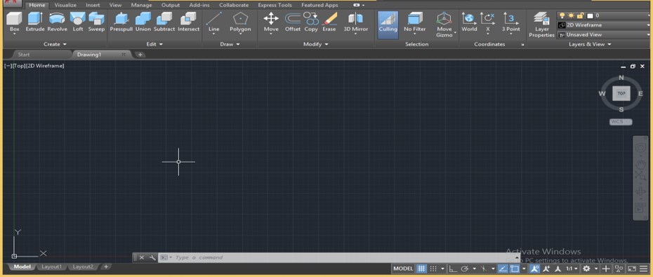
Step 1: At the top of the working screen, we have a ribbon of different tabs which contains many commands for managing the work of this software, below this ribbons; we have a working window in which we can see our current drawing or project, at the right side of this window we have navigation cube which helps us in see our object from different views such as top view, side view, front view, below this at the bottom of the working screen there is some navigation tool for handling work of this software.
Step 2: Now, let us switch our working area to 3D Basics from the Workspace Switching option at the bottom end of the working window.
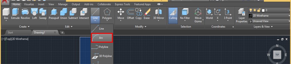
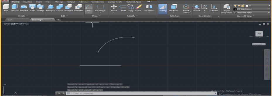
Step 3: Now, let us have the Arc command from the Draw menu of the Home tab by click on it.
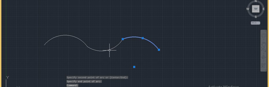
Step 4: And draw three arcs like this of any dimension.
AutoCAD Training (6 Courses, 17 Projects) 6 Online Courses | 17 Hands-on Project | 52+ Hours | Verifiable Certificate of Completion | Lifetime Access4.5 (3,521 ratings)
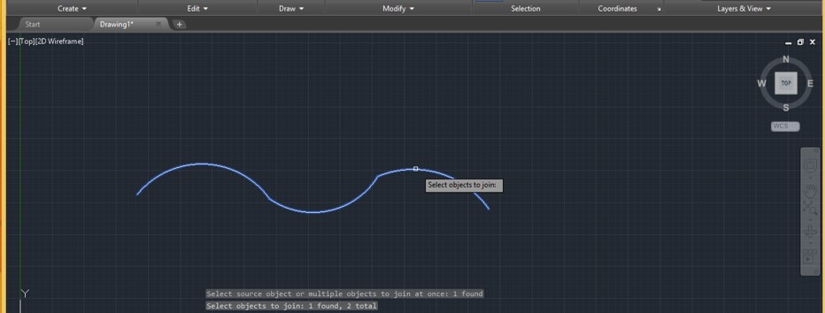
Step 5: Now take the Join command for joining these arcs. For the Join command, type JOIN and press the enter key.
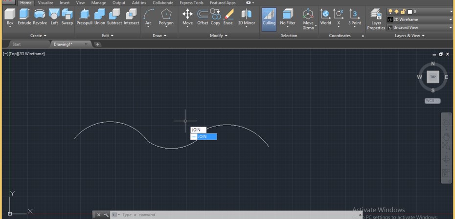
Step 6: Now select all arcs with the cursor of the Join command one by one, then press the enter key for joining them in one arc.
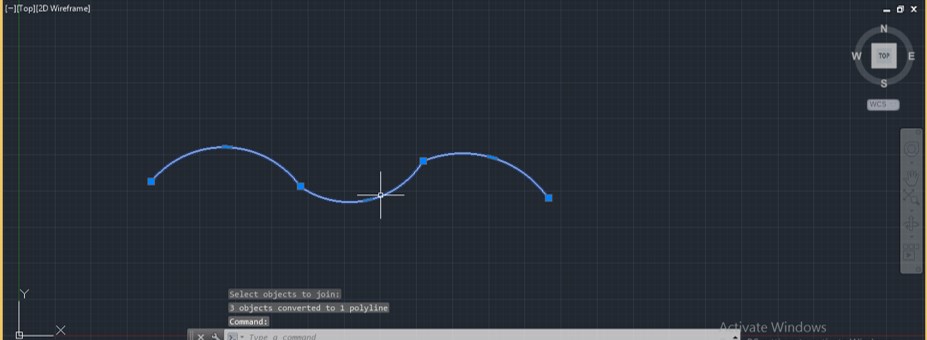
Step 7: It will join like this.
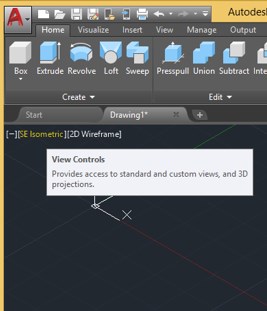
Step 8: Now go to the View Controls options of this software for changing the view and click on it.
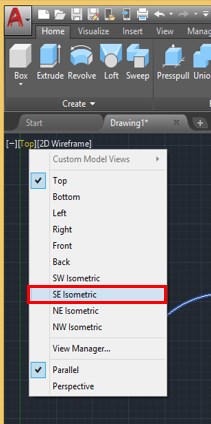
Step 9: A drop-down list will be open; select the SE Isometric option, which is the southeast view from the drop-down list, by click on it.
Step 10: Now, take the Polygon command from the Draw menu of the Home tab by click on it.
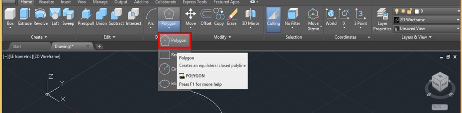
Step 11: Now, it will ask for entering the value of the sides of Polygon. I will take 6 as the side of my polygon shape, then press the enter key.
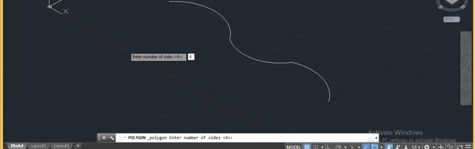
Step 12: Now draw a hexagon by dragging the mouse cursor, or you can give the radius of the circle of this hexagon manually like this, then press the enter key.
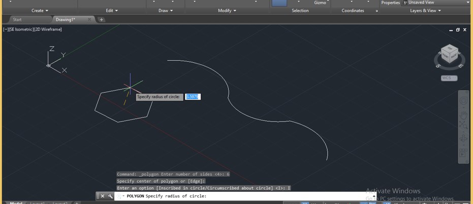
Step 13: Go to go Sweep command of this software which is at the Create menu of Home tab and click on it for having it.
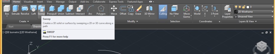
Step 14: Now, it will ask you to select the object which you want to sweep. So I will select my hexagon shape by clicking on it and press enter button on the keyboard.
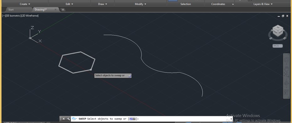
Step 15: Now, it will ask you to select the path along which you want to sweep your shape. I will select this curved line by clicking on it.
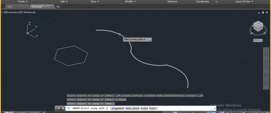
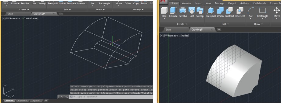
Step 16: Then press the enter button on the keyboard. Once you press the enter button of the keyboard, it will sweep your shape like this. This is a 2d wireframe view of sweep shape.
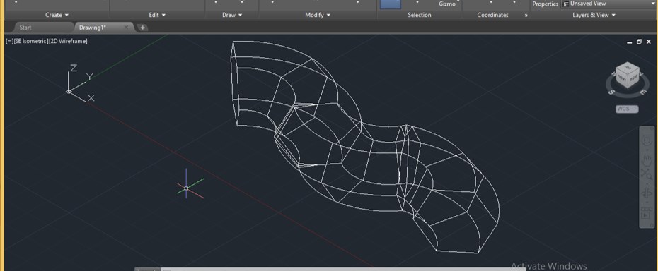
Step 17: For shaded view, go to Visual Style Controls of this software and click on it.
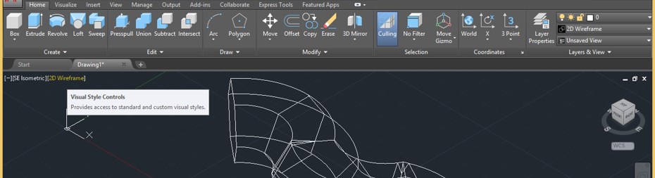
Step 18: A drop-down list will be open; click on the Shaded option of the drop-down list.
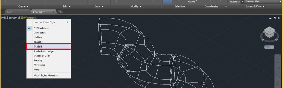
Step 19: Now, it will look like this once you click on the Shaded option. You can go with another option also for different styles.
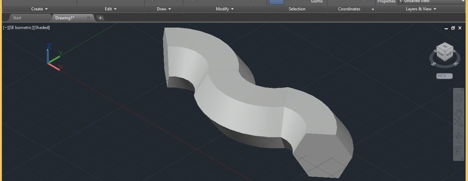
Step 20: Now, let us analyze other options of sweep command. Let us have a rectangle command from the Draw menu of the Home tab by click on it for other options.
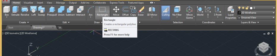
Step 21: And draw a rectangle of any dimensions, then go to View Control of this software and click on it. Now click on the Front option of the list.
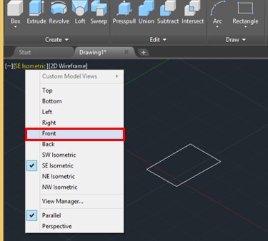
Step 22: Now, take the Arc command from the Draw menu of the Home tab of this software and draw an arc of any dimension like this.
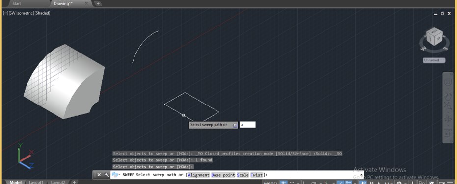
Step 23: Now again, come back to SW Isometric view from View controls option and again take Sweep command from the Create menu of Home tab of this software. Select the rectangle with the sweep command and press the enter key.
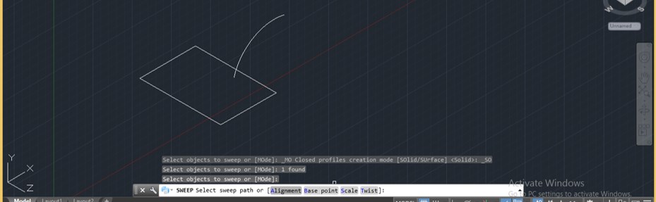
Step 24: Now go to the parameters box of Sweep command, which is at the bottom end of the working window and type A here and press enter button of the keyboard.
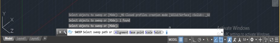
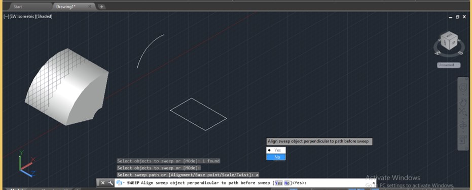
Step 25: Now, it will ask you that would you want to draw a sweep align at the perpendicular section or not. Say yes by pressing the Y key on the keyboard in this box, then press the enter key.
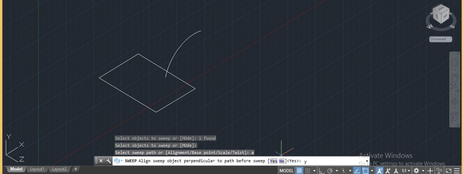
Step 26: Then select a path which is the arc in our drawing, and it will draw a shape like this.
Step 27: Now, let us see what will happen if we say No to the alignment option. Again draw the same shape as we are drawn in the previous.
Step 28: Now again, take the Sweep command and select rectangle, then press enter button of the keyboard. Now press the ‘A’ button, then press the Enter button on the keyboard.
Step 29: Now, it will ask you Yes or No for the alignment option. This time I will say No by typing N in the parameter box then press enter button of the keyboard.
Step 30: Now select the path along which you want to draw sweep and press enter button of the keyboard.
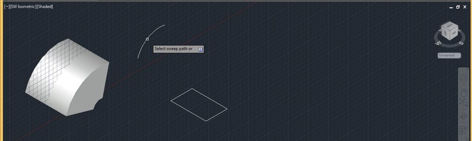
Step 31: Then the sweep will take shape like this, which is not perpendicular to the cross-section of made object. You can see the differences between both objects.
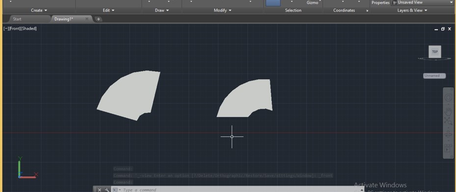
In this way, you can use different options of sweep command and see their variation on sweep object. You can use this command for making effective objects.
Now, after this article, you can understand ‘what is sweep command in AutoCad software and ‘how you can use its option for getting the best result from this command’. You can make a different type of variation in parameters of this command for getting different shape object with this command.
Recommended Articles
Читайте также: