
Подключение digispark к linux
Обновлено: 02.07.2024
Итак начнем с разбора самой платы и ёё возможностей .
ATtiny85 — небольшой микроконтроллер с приличными возможностями и приятными особенностями, включая:
Плата разработчика ATTINY85 предназначена для разработки устройств с минимальными требованиями к периферии и возможностью непосредственного подключения к USB интерфейсу компьютера для программирования и отладки. Для подключения к компьютеру не требуется кабеля - контроллер подключается непосредственно в USB разъем. У контроллера выведено 6 выходов и все они доступны для использования. Два зарезервировано для работы с USB интерфейсом, к одному подключен светодиод. Для разработки можно использовать среду разработки Arduino IDE (OSX/Win/Linux).
Питаться устройство может от USB интерфейса, внешнего источника напряжением 5В и напряжением от 7В до 12В от внутреннего стабилизатора напряжения 5В 500мА. Переключение источника питания происходит автоматически.
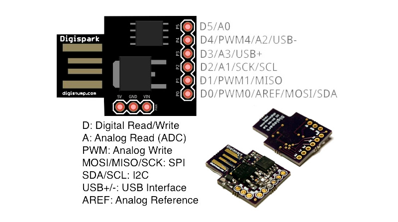
Функции выводов контроллера:
- Р0 - ARef, SDA, DI, PWM
- P1 - DO, PWM
- P2 - D/A, SCK
- P3 - D/A, USB+
- P4 - PWM, D/A, USB-
- P5 - D/A
Характеристики:
- Микроконтроллер: ATTINY85
- Внутренний генератор: 8МГц
- Встроенный умножитель частоты: 8
- Объем памяти программ: 8Кбайт (6Кбайт доступных)
- Аппаратные интерфейсы: SPI, I2C
- ШИМ: 3 канала
- АЦП: 4 канала
- Индикаторы: Питание Состояние (Pin0)
Пинмапинг и распиновка
Покупал я платы на Алиэкспресс :

Устанавливаем своеобразный плагин для среды Arduino (поддерживается начиная с версии 1.6.5).
Вставляем в поле Additional Boards Manager URLs строку
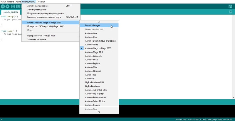
Переходим в меню Инструменты — Boards Manager:
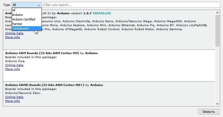
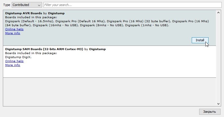
В выпадающем списке Type выбираем Contributed, а затем щелкаем по Digistump AVR Boards, при этом появится кнопочка Install, которую и нажимаем:
Начнется скачивание и установка софта и драйверов. Говорим, что согласны на все:
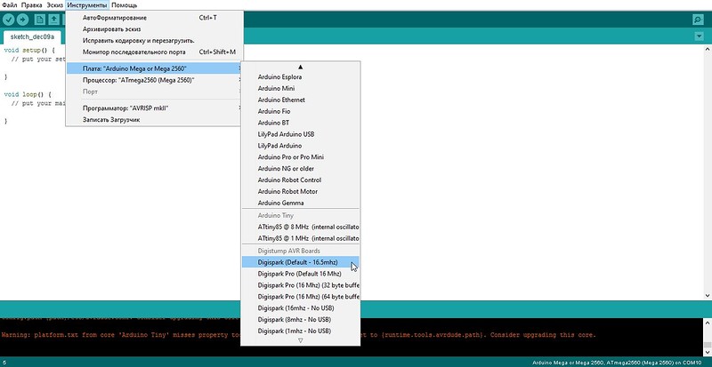
Выбираем рекомендованную для начинающих плату Digispark (Default — 16,5mhz) - выбираем вашу плату :
Теперь можем перейти в раздел примеры - digispark и выбрать понравившийся вам тестовый скетч :
В отличие от классических плат Arduino, эту плату не нужно подключать к компьютеру перед загрузкой прошивки. Наоборот, сначала нужно запустить загрузку из среды Arduino и дождаться приглашения к подключению контроллера. Вот теперь — можно.
Таймаут на загрузку — 60 секунд:
Связано это с особым режимом работы загрузчика: при старте контроллера он ждет загрузки кода через USB в течение 5 секунд, а потом переключается в режим исполнения имеющегося в памяти контроллера кода.
Иными словами, если контроллер подключить к компьютеру до приглашения, то спустя пять секунд он начнет выполнять имеющийся код (если есть), а чтобы загрузить новый, нужно отключить и снова подключить плату к компьютеру.
- В режиме холостого хода (Idle) останавливается ЦПУ при этом продолжают работу статическое ОЗУ, таймер-счетчик, АЦП, аналоговый компаратор и система прерываний.
- В режиме пониженной мощности (Power-down) сберегается содержимое регистров, отключаются все встроенные функции до следующего прерывания или аппаратного сброса.
- В режиме снижения шумов АЦП (ADC Noise Reduction) останавливается ЦПУ и все модули ввода-вывода, кроме АЦП, за счет чего достигается снижение цифровых шумов во время преобразования АЦП.
Рассмотрим назначение выводов (Pin).
Комментарий к рисунку:
- 5, 6, 7, 2, 3, 1 - ножки микроконтроллера ATtiny85.
- PB0-PB5 - цифровые входы/выходы.
- PCINT0-PCINT5 - генерируют одно и то же прерывание - PCINT0, PCINTx- прерывания обслуживает сразу целый порт.
- ADC0-ADC3 - Аналого-цифровой преобразователь (Analog - digital converter)
- PWM0, PWM1, PWM4 - Широтно-импульсная модуляция (Pulse-Width Modulation)
- MOSI, MISO, SCLK - Последовательный периферийный интерфейс (SPI)
- SDA, SCL - Последовательная асимметричная шина (I²C)
- AREF - Предназначен для задания опорного напряжения
- INT0 - Высокоскоростной таймер-счетчик
Платы Digispark ATtiny85 поставляются с загрузчиком Micronucleus и с отключенным выводом сброса (reset (P5)). У некоторых моделей ( купленных на AliExpress) вывод P5 включен как сброс (reset) .
PB3 и PB4 применяются также для прошивки Digispark по USB. К выводу PB3 припаян подтягивающий резистор 1,5kOm.
Меры предосторожности.
При тестировании платы рекомендуется сначала проверить ее с помощью внешнего источника питания. Подключение неисправной Digispark или с замкнутыми выводами может привести к повреждению компьютера.
Настоятельно рекомендуем подключать Digispark через USB-концентратор, который часто ограничивает ущерб, вызванный коротким замыканием на USB-концентраторе.
Digispark не имеет защиты от короткого замыкания или обратной полярности.
Я не несу ответственности за неправильное использование Вами Digispark и другого оборудования.
Разновидности и характеристики Digispark ATtiny85.
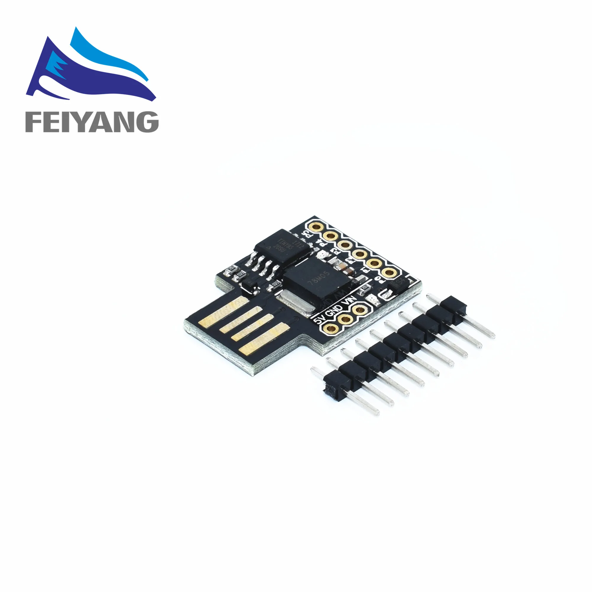
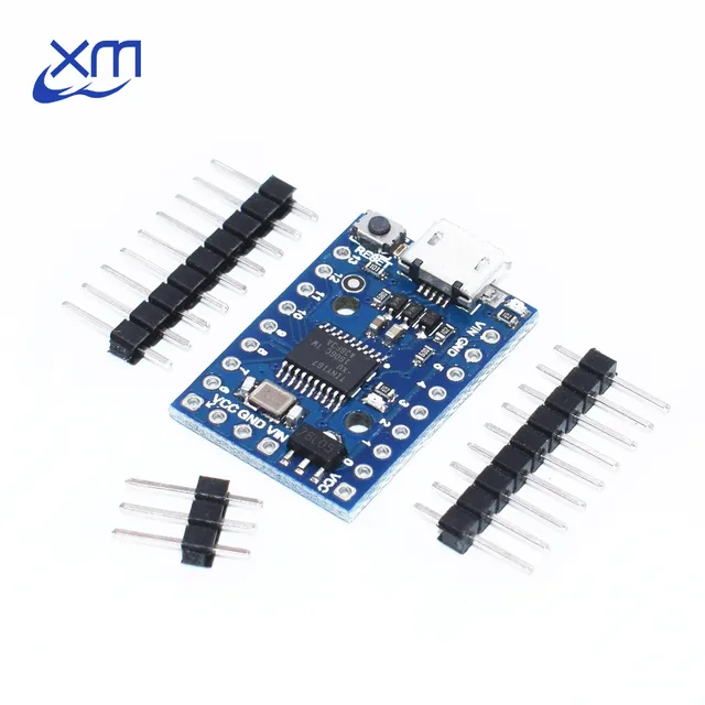
Разновидностей плат Digispark ATtiny85 две.
Первый вариант Digispark ATtiny85 с USB разъемом , который можно подключать непосредственно к USB порту компьютера.
Второй вариант Digispark ATtiny85 с micro USB разъемом , который подключается к компьютеру через переходник USB – micro USB.
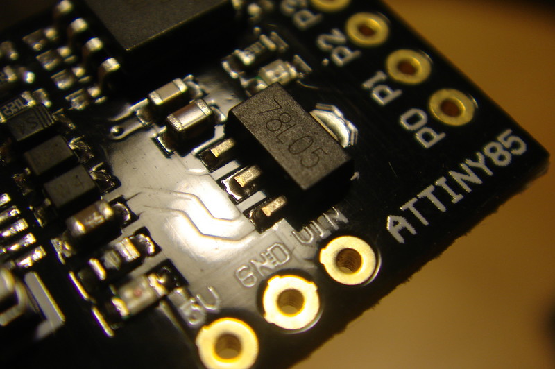
В обоих случаях основой плат Digispark является микроконтроллер ATtiny85-20SU в разновидности корпуса для поверхностного монтажа.
Следовательно, основные характеристики данной платы совпадают с характеристиками ATtiny85, о котором мы подробно говорили в статье " ATtiny13 и ATtiny85. Обзор и программирование с помощью Arduino ".
- Тактовая частота - до 20МГц
- Память программ ( FLASH ) - 8КБ (в реальности около 6КБ, т.к. часть памяти занимает встроенный загрузчик)
- Оперативная память ( SRAM ) - 512 байт
- Энергонезависимая память ( EEPROM ) - 512 байт
Распиновка Digispark ATtiny85
Снизу платы 3 пина: питание 5В, земля и входящее питание до 12В. По словам разработчиков на вход VIN можно подавать до 35В, но лучше не превышать 12В.
Справа размещены 6 пинов ввода-вывода. Все пины умеют работать с цифровым сигналом, пины P2, P3, P4 и P5 могут получать аналоговый сигнал от различных датчиков. P0, P1, P4 могут работать с ШИМ -сигналом. Только во время прошивки нельзя занимать пины P3 и P4 , т.к. они задействованы в работе с USB. А так же пин P1 (в некоторых моделях P5), который задействован под reset .
Большим преимуществом Digispark ATtiny85 по сравнению с «голым» ATtiny85 является возможность прошивки непосредственно из Arduino IDE. Т.е. нет необходимости использовать дополнительный программатор, в качестве которого у нас в одной из предыдущих статей, выступала Arduino UNO. К тому же, наличие USB-интерфейса позволяет не только получать данные с компьютера, но и отправлять данные на ПК, имитируя виртуальную клавиатуру.
К тому же USB-интерфейс позволяет запитать уже прошитую и готовую к работе плату, в том числе с подключенными датчиками, от стандартных зарядок для телефона (в случае варианта платы Digispark ATtiny85 с USB разъемом), либо от USB выхода powerbank.
Обо всём этом мы поговорим в следующих статьях.
Установка библиотеки для работы с Digispark ATtiny85.
Для работы с платой Digispark ATtiny85 в среде разработки Arduino IDE вначале необходимо установить библиотеку.
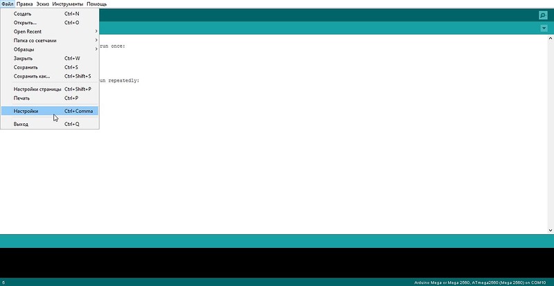
Переходим в меню Файл -> Настройки . И в поле Дополнительные ссылки для Менеджера плат вставляем следующую ссылку:
This part of the Digispark Arduino tutorial series shows how to set up the Arduino IDE to program Digispark ATtiny85 boards in Linux Mint, and should work with other Linux distributions such as Ubuntu. After setting up the software, the board is tested by loading a Blink sketch to it that blinks or flashes the on-board LED.
The basic steps that must be followed to program a Digispark board using the Arduino IDE in Linux Mint are 1) download and install the Arduino IDE, 2) install board support in the Arduino IDE, 3) add your Linux user name to the dialout group, 4) add udev rules to the system and 5) test the installation by loading a sketch to the Digispark board.
Digispark and compatible boards, as shown in the image below, can be programmed from the Arduino IDE in Linux Mint and other Linux distributions such as Ubuntu after following this tutorial.

Instructions in this tutorial and in the video that follows are based on the Digispark programming instructions on the Digistump Wiki and the Linux Troubleshooting page on the Digistump Wiki that includes Ubuntu and Arch troubleshooting steps. Either watch the video below, or follow the instructions below the video.
Arduino IDE Digispark Linux Mint Setup Tutorial Steps
The following steps show how to set up a Digispark board for programming with the Arduino IDE in Linux Mint.
1. Install the Arduino IDE
Download the Linux 64 bits file for 64-bit Linux Intel systems or the Linux 32 bits file for Linux 32-bit Intel systems. There are also equivalent files for 32-bit and 64-bit ARM systems. Unzip the downloaded file, and extract the folder found in the zipped file to a convenient location, such as the Desktop. To run the Arduino IDE application, open the extracted folder and double-click the Arduino executable file.
The image below shows the contents of the folder extracted from the downloaded zipped file, with the Arduino application selected. Simply double-click this file to start the Arduino IDE application.

After double-clicking the Arduino executable file, a dialog box pops up, as shown below. Click the Run button in the dialog box to start the Arduino IDE application.

2. Install the Digispark Board Support Package
Start the Arduino IDE application that you downloaded in the previous step.
Open Preferences Dialog box
From the top menu of the Arduino IDE application, select File → Preferences to open the Preferences dialog box.
Paste the following in the Additional Boards Manager URLs: box of the Preferences dialog box.
The image below shows the Additional Boards Manager URLs field of the Preferences dialog box.

Click the OK button to close the dialog box.
Open Boards Manager Dialog Box
In the Arduino IDE, use the top menu to navigate to Tools → Board → Boards Manager. to open the Boards Manager dialog box.
Type Digispark into the search field at the top of the Boards Manager dialog box that contains the text "Filter your search. " to easily find the Digispark package.
After filtering the packages, Digistump AVR Boards is displayed in the Boards Manager dialog box. Click the Install button at the bottom right of the Digistump item in the dialog box, as shown in the image below.

After clicking the Install button, the package will start installing. This may take a while, depending on the internet speed.
When installation completes, click the Close button at the bottom right of the dialog box.
Books that may interest you:
3. Add Linux User Name to the Dialout Group
In order to be able to program any board from the Arduino IDE, the Linux user must be added to the dialout group.
Open a terminal window in Linux and enter the following command:
Enter your Linux password when prompted.
You will need to log out and then log back in, or reboot, for the changes to take effect.
4. Add udev Rules to the System
To be able to program the Digispark board from the Arduino IDE in Linux, udev rules must be added to the system. This is done by creating a file in /etc/udev/rules.d/ that contains the rules.
In order to be able to create this file in the file system, you will need root permission. This can be done by opening a terminal window and entering:
After running the above line to start the nano editor, copy all of the udev rules code from the listing above and paste them into the nano editor using the keyboard combination Ctrl + Shift + V.
In the nano editor, press Ctrl + O and then press the Enter key save the file and then Ctrl + X to exit the application.
Finally enter the following in the terminal window to reload the udev rules.
5. Testing the Digispark Linux Mint Installation
Uploading a sketch to a Digispark board works differently from other Arduino boards. The board must not be plugged into a USB port, but must first be selected in the Arduino IDE. No port is selected. The sketch is uploaded, and when a prompt appears in the Arduino IDE, the board is plugged into a USB port. The following tutorial steps show how to load a sketch to a Digispark board.
Digispark Blink Sketch
The following sketch works on both Model A and Model B Digispark boards. The difference is that Model A boards have the on-board LED connected to pin 1, while the Model B boards have the on-board LED connected to pin 0.
Copy the following sketch and paste it into the Arduino IDE window. Save it as digispark_blink or a name of your choice.
Select the Digispark Board in the Arduino IDE
From the top menu in the Arduino IDE, select Tools → Board → Digistump AVR Boards → Digispark (Default - 16.5MHz) to select the Digispark board.
Load the Blink Sketch to the Digispark Board
Click the Arduino Upload button on the top toolbar before plugging the Digispark board into a USB port.
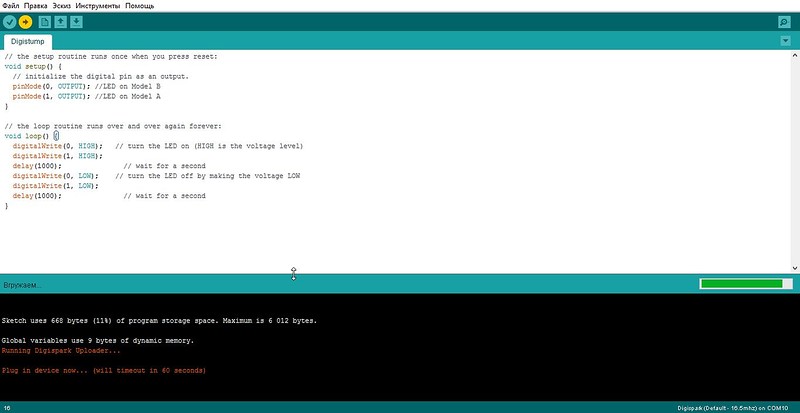
Wait for the prompt at the bottom of the Arduino IDE window, as shown in the following image.

When the prompt Plug in device now. (will timeout in 60 seconds) appears, plug the Digispark board into a USB port of the computer.
After the sketch finishes uploading, a success message running: 100% complete and >> Micronucleus done. Thank you! appears at the bottom of the Arduino IDE window, as can be seen in the following image.
This part of the Digispark Arduino tutorial series shows how to set up the Arduino IDE to program Digispark ATtiny85 boards in Windows 10. After setting up the software and drivers, the board is tested by loading a Blink sketch to it that blinks or flashes the on-board LED.
The basic steps that must be followed to program a Digispark board using the Arduino IDE in Windows 10 are 1) download and install the Arduino IDE, 2) install board support in the Arduino IDE, 3) install Windows drivers and 4) test the installation by loading a sketch to the Digispark board.
Digispark and compatible boards, as shown in the image below, can be programmed from the Arduino IDE in Windows 10 after following this tutorial.

Instructions in this tutorial and in the video that follows are based on the Digispark programming instructions on the Digistump Wiki. Either watch the video below, or follow the instructions below the video.
Arduino IDE Digispark Windows 10 Setup Tutorial Steps
The following steps show how to set up a Digispark board for programming with the Arduino IDE in Windows 10.
1. Install the Arduino IDE
This can be done by either downloading and running the Windows Installer, or by downloading the Windows ZIP file. If the Windows ZIP file is downloaded, it must simply be unzipped, and the folder extracted to a convenient location, such as the Windows Desktop. Just open the extracted folder and double-click the Arduino executable file to start Arduino.
The image below shows the contents of the folder extracted from the downloaded zipped file, with the Arduino application selected. Simply double-click this file to start the Arduino IDE application.

2. Install the Digispark Board Support Package
Start the Arduino IDE application that you downloaded in the previous step.
Open Preferences Dialog box
From the top menu of the Arduino IDE application, select File → Preferences to open the Preferences dialog box.
Paste the following in the Additional Boards Manager URLs: box of the Preferences dialog box.
The image below shows the Additional Boards Manager URLs field of the Preferences dialog box.

Click the OK button to close the dialog box.
Open Boards Manager Dialog Box
In the Arduino IDE, use the top menu to navigate to Tools → Board → Boards Manager. to open the Boards Manager dialog box.
Type Digispark into the search field at the top of the Boards Manager dialog box that contains the text "Filter your search. " to easily find the Digispark package.
After filtering the packages, Digistump AVR Boards is displayed in the Boards Manager dialog box. Click the Install button at the bottom right of the Digistump item in the dialog box, as shown in the image below.

After clicking the Install button, the package will start installing. This may take a while, depending on the internet speed.
When installation completes, click the Close button at the bottom right of the dialog box.
Books that may interest you:
3. Install the Digispark Windows 10 Drivers
Unzip the Digistump.Drivers.zip file downloaded from the above link and extract the Digistump Drivers folder from it.
Open the unzipped Digistump Drivers folder, as shown in the following image.

Double-click either DPinst64.exe on a 64-bit Windows computer, or DPinst.exe on a 32-bit Windows computer to install the Digispark drivers.
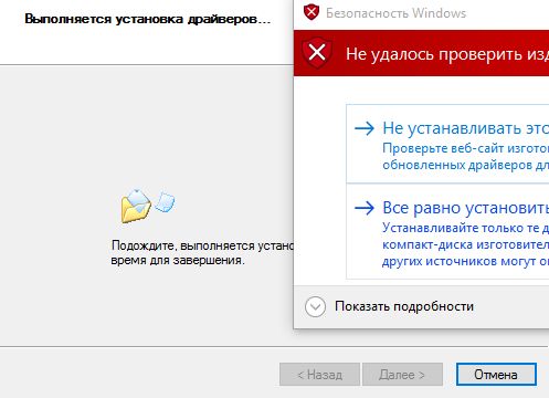
When prompted to install the driver with the following dialog box, click the Install button.


If a dialog box pops up that displays Windows can't verify the publisher of this driver software, click the Install this driver software anyway button.
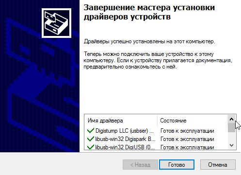
After the driver installation has finished, click the Finish button in the Device Driver Installation dialog box.
4. Testing the Digispark Driver Windows 10 Installation
Uploading a sketch to a Digispark board works differently from other Arduino boards. The board must not be plugged into a USB port, but must first be selected in the Arduino IDE. No port is selected. The sketch is uploaded, and when a prompt appears in the Arduino IDE, the board is plugged into a USB port. The following tutorial steps show how to load a sketch to a Digispark board.
Digispark Blink Sketch
The following sketch works on both Model A and Model B Digispark boards. The difference is that Model A boards have the on-board LED connected to pin 1, while the Model B boards have the on-board LED connected to pin 0.
Copy the following sketch and paste it into the Arduino IDE window. Save it as digispark_blink or a name of your choice.
Select the Digispark Board in the Arduino IDE
From the top menu in the Arduino IDE, select Tools → Board → Digistump AVR Boards → Digispark (Default - 16.5MHz) to select the Digispark board.
Load the Blink Sketch to the Digispark Board
Click the Arduino Upload button on the top toolbar before plugging the Digispark board into a USB port.
Wait for the prompt at the bottom of the Arduino IDE window, as shown in the following image.

When the prompt Plug in device now. (will timeout in 60 seconds) appears, plug the Digispark board into a USB port of the computer.
After the sketch finishes uploading, a success message running: 100% complete and >> Micronucleus done. Thank you! appears at the bottom of the Arduino IDE window, as can be seen in the following image.
Читайте также: